LifterMate™: Moving Beyond the Hoyer-Style Portable Patient Lift
Robert M. Levy, Ph.D. Criterion Health, Inc. and Richard Nelson, B.F.A. Easter Seals Rehabilitation Center and Criterion Health, Inc.
ABSTRACT
Hoyer-style portable patient lifts are used to transfer patients who have difficulty or cannot transfer independently, for example, between a wheelchair and a bed. However, since they are unstable outside the footprint of their base, they cannot be used, for example, for transfers into and out of a bathtub. LifterMate™ uses an external stabilization system to address this serious shortcoming. In addition, LifterMate™ incorporates additional design innovations that make it more maneuverable and stable than existing Hoyer-style lifts. The processes underlying the design and development of LifterMate™, incorporating extensive end-user input, are described. In addition, the results of pilot testing showing the benefits of the innovations are presented.
KEYWORDS
Transfer technology, patient lifters, wheelchair transfers
BACKGROUND and SIGNIFICANCE
LifterMate™ addresses the historic challenge for a portable lifter design for transferring individuals who cannot or have difficulty transferring independently. The original Hoyer lift patent was granted in 1958. Portable patient lifts continue to be variations on the Hoyer-style lift. A major limitation is that the lifter is only stable for transfers in which the client’s center of mass is within the footprint of the base. This restriction precludes, for example, a transfer into and out of a bathtub.
The design and development of LifterMate™ was undertaken to address this challenge. Further analysis of the Hoyer-style lift identified additional opportunities for design improvements that would lead to not only a portable patient lifter with the capability of transfers outside the footprint of the base but also to a lifter that is easier to maneuver and more stable, which increases the safety for the caregivers and clients.
In this paper we describe the processes by which LifterMate evolved as well as the preliminary outcomes for the design improvements.
METHODS AND RESULTS
End-User Input
An essential ingredient of the design process was the inclusion of end-user input, in which the end users for this product are 1) wheelchair clients who cannot or have difficulty transferring independently, 2) caregivers, and 3) professional staff, for example, physical and occupational therapists. Four rounds of focus groups were conducted throughout the design and development stages–first using conceptual drawings and then later full-scale models and finally a full-scale bench model.
End-user input fell into broad categories:
- Specific preferences about designs:
- These helped eliminate many design concepts. For example a preference to avoid over the head activity and concerns about required ceiling bracket or anything attached to the floor.
- Focus group discussion helped address one major design issue. Once the lifter is stabilized, deployment may require the client to undergo a 90 degree or 180 degree rotation. Clients alleviated our concerns that this would cause them to be nervous or fearful, as long as the rotation was done smoothly and slowly.
- General concerns about lifters and lifter use:
- Caregiver turnover is high, but the client remains the same.
- The single most important concern is safety and ease of use, especially because of caregiver turn over.
- End users emphasized the need to minimize clutter: keep the area around the base open to provide access to the client, keep the area around the posts compact, etc.
- Make the stabilization arm easy to connect and disconnect to a wall bracket. The connection should be robust in that it does not require careful alignment to position properly.
- When not in use, the stabilization arm should fold out of the way.
- Don’t paint it gray!!!
- If possible, make LifterMate portable, i.e., for travel.
- What to emphasize as the project moves from bench model to a prototype (SBIR Phase II):
- Make it failsafe. Build in safety mechanisms that, for example, prevent moving the client outside the area of the base before the stabilizer arm is properly connected.
- Provide training materials such as manuals and DVDs. Try to make its use intuitive,
- As always – stability, stability, stability.
- End users are appreciative of the opportunity to participate in the design process for products that may improve the quality of their lives.
Development of the LifterMate Preliminary Prototype
-
The first bench model. The development of LifterMate was through an NIH SBIR grant. The Phase I project was to demonstrate the feasibility of an external stabilization system for a Hoyer-style lift that would allow transfers outside the footprint of the base. Numerous design concepts were generated for ways in which to stabilize the lifter. End-users were critical of many: For example–stabilization using a ceiling bracket was not a good idea because it would require caregivers to work over their head, false or suspended ceilings would not provide a suitable anchor, ceilings vary in height; a floor bracket would become a trip hazard for caregivers and affect the integrity of the floor, which is problematic in a wet environment. Engineering considerations at the Center for Assistive Technology and Environmental Access (CATEA) at Georgia Tech eliminated others. For example–a stabilizing bracket over the wall of a bathtub might, over time, and repetitive strain, crack the tub wall.

Figure 1. First LifterMate Bench Model (Click for larger view)
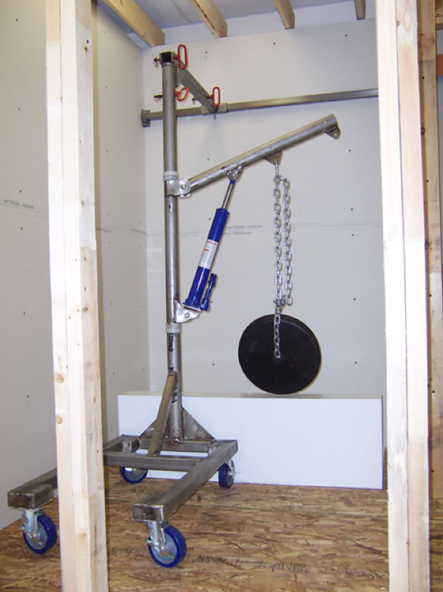
The preferred design was a stabilization arm that could be a part of the lift and attached to a fixed wall mounted bracket for transfers outside the footprint of the base. A bench model, shown in Figure 1, was constructed and the feasibility of the concept established with testing at CATEA and the Easter Seals Rehabilitation Center, Evansville, IN. Feasibility was defined as successfully moving weights up to 113kg in paths that simulated transfers into and out of a bathtub.
-
The second bench model. The first bench model was overbuilt. Although it allowed a fair test of the feasibility of LifterMate, the strength of the materials far exceeded what might be used in the construction of a production product. Since a State of Indiana 21st Century Matching Funds grant was available, a second bench model was designed and constructed. In designing the second bench model, a complete analysis of the lifter components was completed in order to identify potential design issues and opportunities for design improvements that would address the maneuverability and stability concerns end-users had raised. Two changes were tested for the second bench model.
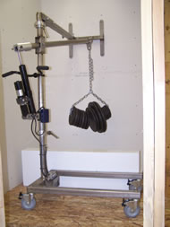
Figure 2. Second LifterMate Bench Model (Click for larger view) - Placement of the actuator. Typical lifter bases are 106 cm (42 inches) long. Almost all Hoyer-style portable lifts have the actuator placed on the front side of the lifter post, which takes up space that the client might otherwise occupy. Placement of the actuator on the rear side of the lifter post would free-up at least 15 cm (6 inches) of space within the footprint of the base. The reduced base length would increase maneuverability, especially in small bathrooms. In order to accomplish this an electric over hydraulic actuator was used. This actuator uses a 12V motor-driven hydraulic pump and a valve system that allows hydraulic fluid to be pumped two ways to push a rod in or out of the cylinder. Therefore the load on the lifter arm (client) is held in place by hydraulic pressure rather than a mechanical linkage, as in a typical electro-mechanical linear actuator. This is a requirement of the ISO 10535 Hoist Standards, specifically section 4, standard 4.3.1.19. A relief valve allows the load (client) to be safely lowered if the electric pump fails. A picture of the second bench model with the actuator on the rear side of the lifter post in shown in Figure 2.
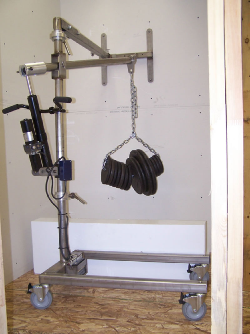
The feasibility testing transferring weights of up to 113 kg was successfully completed with the new bench model.
-
Center load-bearing wheels. Hoyer-style lifts typically have a set of four swiveling casters that are attached to the base for mobility. Initial push forces required to align the casters directionally and to overcome caster bearing friction are substantial.
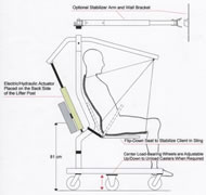
Figure 3. Schematic of LifterMate with Center Load-Bearing Wheels (Click for larger view)
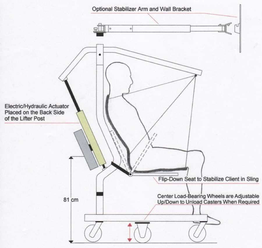
A second modification to “Junior” was the addition of a set of center load-bearing wheels that can be adjusted (raised and lowered) to allow them to bear weight and reduce the load on the front and rear casters. The center load-bearing wheels are never lowered far enough to raise the front and rear casters off of the ground. They are simply lowered enough to reduce the load on the casters to minimize strain on the bearings and allow for more free caster movement. A schematic of LifterMate with the center load-bearing wheels is shown in Figure 3.
A series of pilot tests were conducted at the Easter Seals Rehabilitation Center to determine the benefits of the center load-bearing wheels. The push forces required under different load and surface conditions and the time to roll a fixed course are shown in Table 1 with and without the center load-bearing wheels engaged and bearing weight.
Test |
Load |
Center load-bearing Wheels |
|||
|---|---|---|---|---|---|
| Without Carpet Mean (N) | With Carpet Mean (N) | Without Vinyl Mean (N) | With Vinyl Mean (N) | ||
Forward push force from stop: casters in reversed position |
68.0 |
105.5 |
55.2 |
86.3 |
43.2 |
Forward push force from stop: casters in forward position |
68.0 |
89.0 |
57.9 |
73.0 |
38.7 |
Push force required to maintain forward motion |
68.0 |
44.5 |
35.6 |
22.3 |
22.3 |
Time to roll 4.57 m, turn 90 degrees through a doorway, and roll 1.52 m |
68.0 |
17.7 sec |
12.0 sec |
Test not conducted |
Test not conducted |
To start from a stop on carpet and vinyl required approximately 43% and 44% less push force respectively with the center load-bearing wheels lowered and bearing weight. To maintain forward motion once moving on carpet required approximately 20% less push force with little difference on vinyl. In addition, a simple test of maneuverability on carpet, making a 90 degree turn through a narrow doorway, showed that it was completed in approximately 30% less time with no alignment corrections required using the center load-bearing wheels, compared to three back and forth maneuvers required without the center load-bearing wheels. The results support further development of the center load-bearing drive wheels as a way to increase the maneuverability and ease of handling of portable patient lifters. When deployed, they allow the lifter to track straighter and to turn more predictably, improving overall lifter maneuverability. Reducing the forces required to start the lifter in motion will increase stability from the client’s perspective and decrease musculoskeletal strain for the caregiver.
DISCUSSION
With the use of an external stabilization arm and wall mounted bracket(s), it is feasible to build a lifter that allows the transfer of a wheelchair client outside the footprint of its base. Doing so dramatically increases the options and opportunity available to the client, whether to experience a bath, to use a bed that is not raised off the floor, to get on or off the floor, to access a regular toilet, or to get onto or off a chair. Although multiple uses would require the mounting of multiple wall brackets, their cost and installation will be relatively low compared to the potential improvement in the client’s quality of life.
The reduced length of the base with the inclusion of the rear placement of the actuator and the addition of the adjustable center load-bearing wheels means that LifterMate will provide the same, but improved, functionality, maneuverability, and safety as existing lifters. When commercialized, it will be possible to purchase LifterMate either as a traditional, improved portable lifter or as a traditional, improved portable lifter with the optional external stabilization system to provide, e.g., transfers into and out of a bathtub.
ACKNOWLEDGEMENTS AND IP
This project was funded by NIH SBIR Phase I grant R43 HD056605-01 and by a State of Indiana 21st Century Matching Funds grant to Criterion Health, Inc.
Criterion Health, Inc. has, based on the results of patentability searches, patent pending status for 1) LifterMate with the externalization stabilization system and 2) for LifterMate with the adjustable center load-bearing wheel system. A patentability search suggests that the placement of the actuator on the rear side of the lifter post is already identified in some prior art (it appears to be a standard electro-mechanical actuator in the patent drawings, which would not meet the ISO Hoist Standards). Rear placement of the actuator is not anticipated to be a patent infringement. Trademark protection for LifterMate™ has been obtained.